Pad HPD test beam September 1999 |
This page provides information concerning the beam tests scheduled for the period 7 - 14 July 1999. The tests will be performed in the X7 area of the SPS complex. The plan is to test a Pad HPD with Viking readout in a Cherenkov radiator set-up, where C2F6 or C4F10 gas will be used as light emitting medium.
The set-up consists of a gas radiator volume of 2 m radiator length, equipped with a tilted spherical mirror of 1 m focal length. The HPD is situated in the focus, outside the particle beam.
The beam is defined by 2 scintillator pairs in front of and behind the radiator. In addition 3 silicon pad planes are installed in front of the radiator and one plane behind it. The preliminary configuration of the set-up looks like this...
A technical drawing of the radiator vessel is shown below...
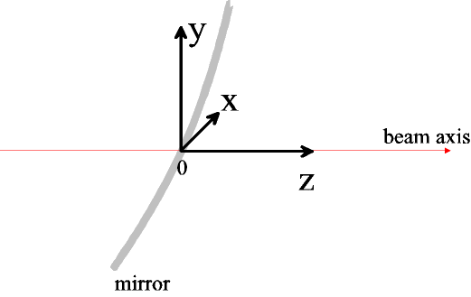
The global coordinate system has its origin at the intersection of the beam axis and the mirror.

The arrangement of the components and concrete blocks is shown below...
The data acquisition system consists of the following VME modules:
| SEQSI: | Sequencer, defines hold + clocking signal for Viking chips |
| C-RAMS: | Digitization of sampled Viking signals, pedestal subtraction, zero suppression |
| RIO: | VME based UNIX processor, reads C-RAMS, sends data as binary files to HP workstation for further processing. |
Any "online" monitoring is based on the binary files arriving at the HP work station. A first description of the online software can be found here.
The following tools are under development:
| TCL/TK based display of HPD |
| TCL/TK based display of the 4 beam telescopes |
| Monitoring of efficiencies, rates, occupancies |
| Reconstruction of tracks and photons, calculation of Cherenkov angles |
| X7 test beam page |
| HPD Si sensor pad map |
| Beam telescope strip map |
Last updated by CJ: 07/06/01